
Автоматизация в настоящее время является очень популярной областью., в которых серводвигатели играют важную роль. Они обычно используются для привода компонентов, требующих точного контроля скорости или положения в проектах.. Разработчики средств автоматизации часто сталкиваются с проблемами выбора двигателя в соответствии с широким спектром требований применения.. Тем временем, поставщики предлагают широкий выбор двигателей с многочисленными параметрами. Ниже я предоставлю краткое описание нескольких ключевых аспектов, которые помогут вам выбрать наиболее подходящий двигатель..
1.Сценарии применения
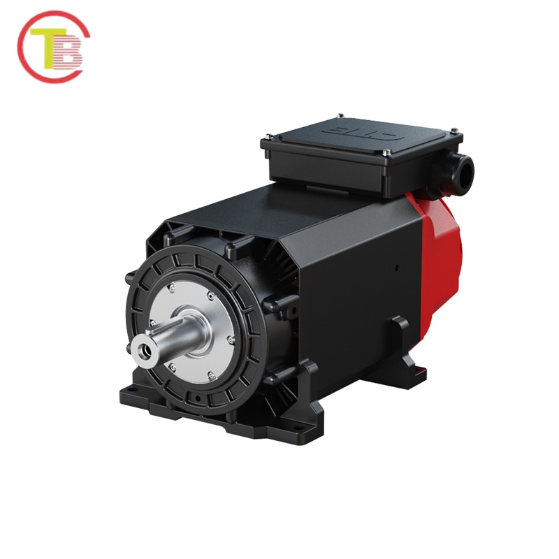
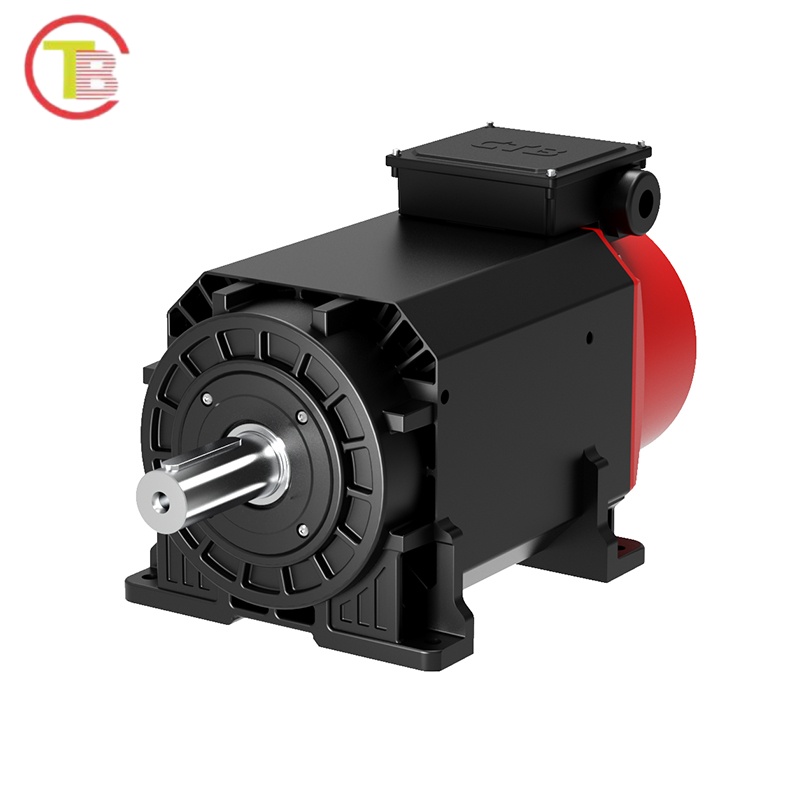
Control motors in the automation field can be classified into servo motors, шаговые двигатели, двигатели переменной частоты, и т. д.. Servo motors are selected for components that require relatively precise speed or position control.
The control scheme of an inverter combined with a variable-frequency motor changes the motor speed by adjusting the frequency of the power supply input to the motor. This method is generally only used for motor speed regulation.
Comparison between servo motors and stepper motors:
- Servo motors use closed-loop control, while stepper motors use open-loop control.
- b) Servo motors use rotary encoders for precision measurement, whereas stepper motors rely on step angles. At the general product level, the precision of servo motors can be hundreds of times higher than that of stepper motors.
- c) Their control methods are similar (pulse or direction signals).
2.Power Supply
В зависимости от источника питания, servo motors can be divided into AC servo motors и DC servo motors.
Selection between them is relatively straightforward. For general automation equipment, the client usually provides a standard 380V industrial power supply or 220V power supply. In such cases, a servo motor matching the available voltage can be chosen directly, avoiding the need for power conversion.
Однако, some equipment — such as shuttle cars in automated warehouses and AGVs — is mobile and mostly equipped with its own DC power supply, so DC servo motors are commonly used.
3.Brake
According to the design of the motion mechanism, it is necessary to consider whether the motor will tend to reverse during a power failure or at standstill.If a reverse tendency exists, a servo motor with a brake should be selected.
4.Selection Calculation
Before performing selection calculations, first determine the position and speed requirements at the end of the mechanism, then confirm the transmission structure. The servo system and corresponding reducer can then be selected.
During the selection process, the following parameters are mainly considered:
4.1 Power and Speed
Calculate the required power and speed based on the mechanical structure and the speed and acceleration requirements of the final load.Note that the reduction ratio of the reducer must usually be matched with the speed of the selected motor.
In actual selection — for example, for horizontal motion loads — the formula P=T×N/9549 often cannot provide an accurate result (due to uncertain friction and windage coefficients in various transmission mechanisms), making precise torque calculation difficult.In practice, it has been found that the peak power demand for servo motors usually occurs during acceleration and deceleration.
Поэтому, the required motor power and reducer ratio can be quantitatively calculated using:T=F×R=m×a×R where:
м: load mass
а: load acceleration
Р: load rotation radius
The following points should be noted:а) Power margin factor of the motor.b) Transmission efficiency of the mechanism.c) Whether the input and output torque of the reducer meet the requirements with an adequate safety factor.d) Possibility of increasing speed in later stages.
Official Account: Mechanical Knowledge Network – Sharing Knowledge, Delivering Value.
It is worth mentioning that in traditional industries such as cranes, ordinary induction motors are used, with no strict acceleration requirements, so empirical formulas are applied for calculation.
Примечание: For vertically moving loads, remember to include gravitational acceleration in calculations.
4.2 Инерционное согласование
To achieve high-precision load control, the inertia matching between the motor and the system must be considered.There is no universally unified explanation online for why inertia matching is necessary. Due to limited personal understanding, no further explanation will be given here. Interested readers may conduct their own research and share their findings.
Inertia matching principle:The ratio of the system inertia (referred to the motor shaft) to the motor inertia should generally not exceed 10 (per Siemens standards).A smaller ratio improves control stability but requires a larger motor, reducing cost performance.
For specific calculation methods, please refer to university-level Theoretical Mechanics if unclear.
4.3 Precision Requirements
Verify whether the control precision of the motor — after accounting for the reducer and transmission mechanisms — can meet the load requirements.The backlash of reducers or certain transmission components must also be considered.
4.4 Control Matching
This mainly involves communication and confirmation with electrical designers, such as:
Whether the communication protocol of the servo driver is compatible with the PLC.
The type of encoder and whether data output is required.
Finally, servo motor manufacturers now provide technical support. As long as you provide parameters such as load, скорость, and acceleration requirements, their professional technical team will help you calculate and select the appropriate servo motor automatically, which is very convenient.