
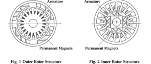
Permanent magnet synchronous motors can be divided into outer rotor and inner rotor structures according to the position of the rotor inside the motor. The distinction lies in whether the inner part or the outer part rotates. If the inner part rotates, it adopts an inner rotor structure; if the outer part rotates, it features an outer rotor structure.
Generally speaking, the rotating component fitted with magnetic steel is the rotor, while the stationary component fitted with coils is the stator. Let us discuss the differences between inner rotor and outer rotor permanent magnet motors.
In practical applications, the differences between inner rotor and outer rotor motors are listed as follows:
Difference in rotating position. For an inner rotor motor, the driving component rotates inside the motor while the housing remains stationary. For an outer rotor motor, the inner part stays static and the outer housing rotates. Normally, the part embedded with magnetic steel (permanent magnets) rotates, whereas the coil part remains stationary. The difference between outer rotor and inner rotor structures can also be distinguished by the embedding process and location of permanent magnets.
Volume of permanent magnets. Outer rotor motors adopt smaller permanent magnets with shorter axial dimensions, delivering favorable operational stability of the system. Inner rotor motors require larger permanent magnets with correspondingly larger axial dimensions and higher center of gravity, leading to poorer operating stability.
Rotational speed. Taking identical brushless DC motors as an example, inner rotor motors achieve significantly higher rotational speeds than outer rotor motors.
Application scenarios. Inner rotor motors are widely applied in power machinery such as motors, generators, gas turbines and compressors. Outer rotor motors are usually mounted inside impellers to perform heat dissipation and cooling functions.
For outer rotor motors, the stator is fixed at the middle section of the shaft and remains stationary, and the rotor rotates around the outer circumference of the stator. They also belong to the radial air-gap flux structure. Compared with inner rotor motors, the positions of the rotor and stator are swapped. Figure 1 shows the plan view of an outer rotor generator. The stator located inside the motor is defined as the inner stator, and the rotor arranged on the outer periphery of the motor is called the outer rotor.
Direct-Drive Outer Rotor Permanent Magnet Wind Generator
The following introduces the composition and structure of direct-drive outer rotor permanent magnet wind turbine generators, and illustrates the construction via a permanent magnet outer rotor generator model. The left diagram in Figure 3 displays the inner stator core. The stator core is laminated from silicon steel sheets with excellent magnetic permeability. Numerous slots are arranged on the outer circumference of the stator core, where generator windings are embedded. The windings are distributed in accordance with three-phase rules.
Generally, large direct-drive wind generators are equipped with outer rotors having 30 to 40 pole pairs, and the stator slot number ranges from approximately 180 to 240. To clearly demonstrate the structure of the inner stator core, the number of coil slots in this model is far less than that of actual direct-drive generators.
The stator core is mounted on the stator support. One end of the stator support is provided with a flange for mounting onto the nacelle base, and the other end is fitted with the outer rotor shaft, which also serves as the main shaft of the wind generator. The main shaft bears the weight of the entire wind wheel and outer rotor as well as wind loads, so the main shaft and flange plate must possess high mechanical strength.
The structure is displayed from two perspectives. Shaped like a barrel sleeving the outer side of the stator, the outer rotor is manufactured from ferrous materials with good magnetic conductivity. Poles made of permanent magnets are fixed on the inner circumference of the “barrel”, which acts as the rotor yoke. One merit of this structure is that the magnetic poles can be fixed easily and prevented from falling off under centrifugal force. The outer rotor yoke is fastened onto the rotor hub.
Mounting the outer rotor onto the generator main shaft forms a complete outer rotor generator, whose structure is shown from two perspectives in the figure below. The rotor hub not only secures the outer rotor but also carries the entire wind wheel and withstands heavy loads. For this reason, it is installed on the generator main shaft through two large bearings.
Advantages and Disadvantages of Inner Rotor and Outer Rotor Motors
Inner rotor motor advantages: Light fan blades, easy motor manufacturing and assembly, and lower costs.
Disadvantages: Fast temperature rise, high power consumption, unstable voltage that may easily cause motor damage, and short service life.
Outer rotor motor advantages: Capable of fully enclosed design; quick startup and acceleration, low power consumption, high efficiency and long service life.
Disadvantages: Poor sealing performance, large rotor inertia, high noise level, and stringent requirements for dynamic balance.